HAMMER
3D Printed Wheelchair
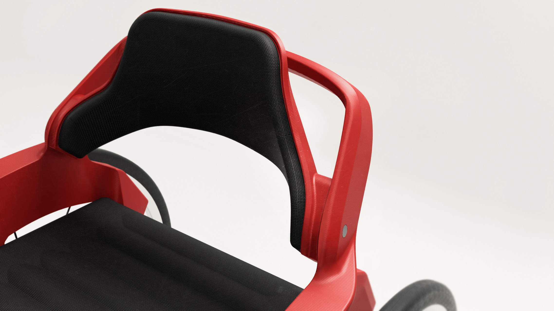
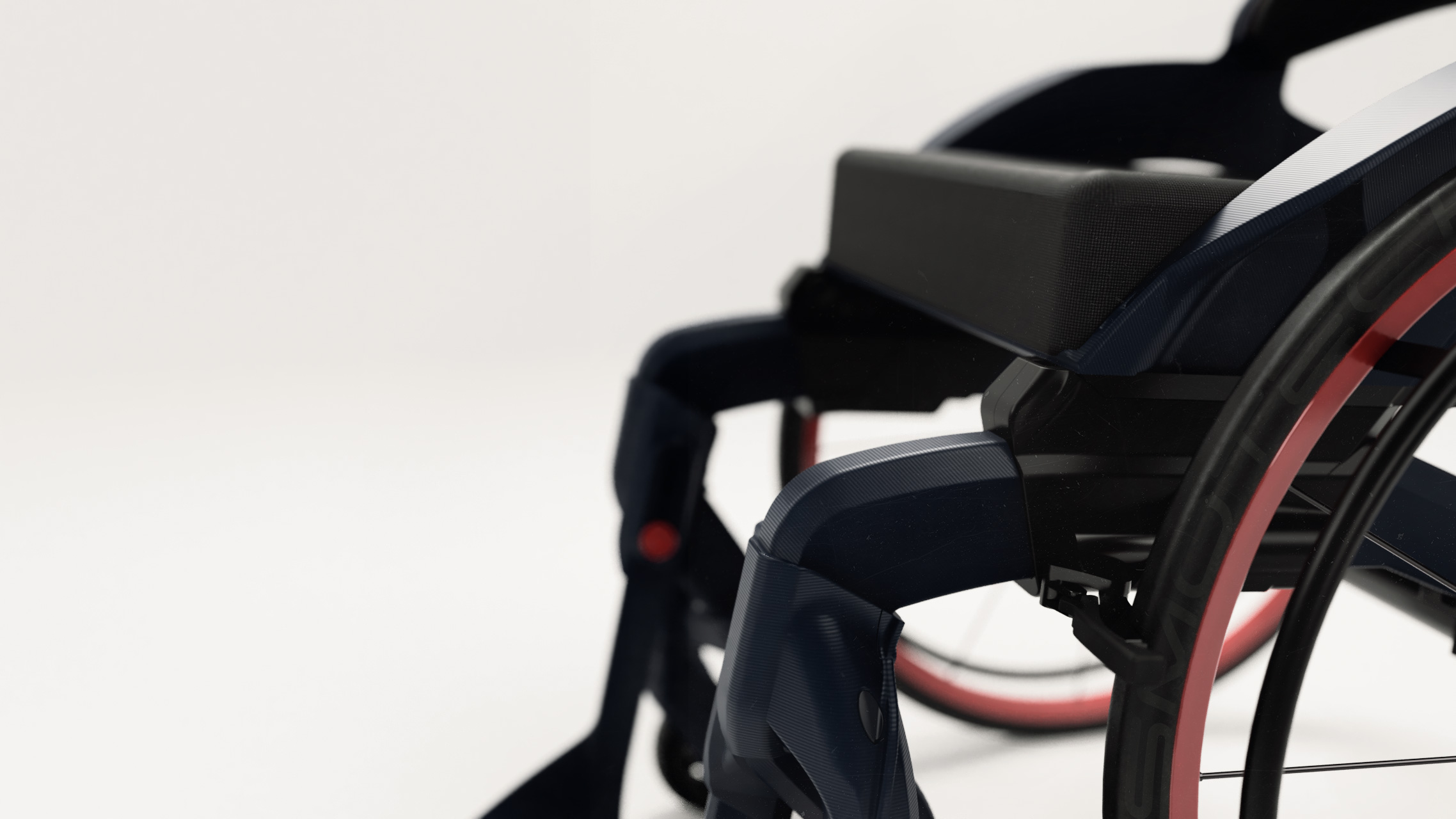
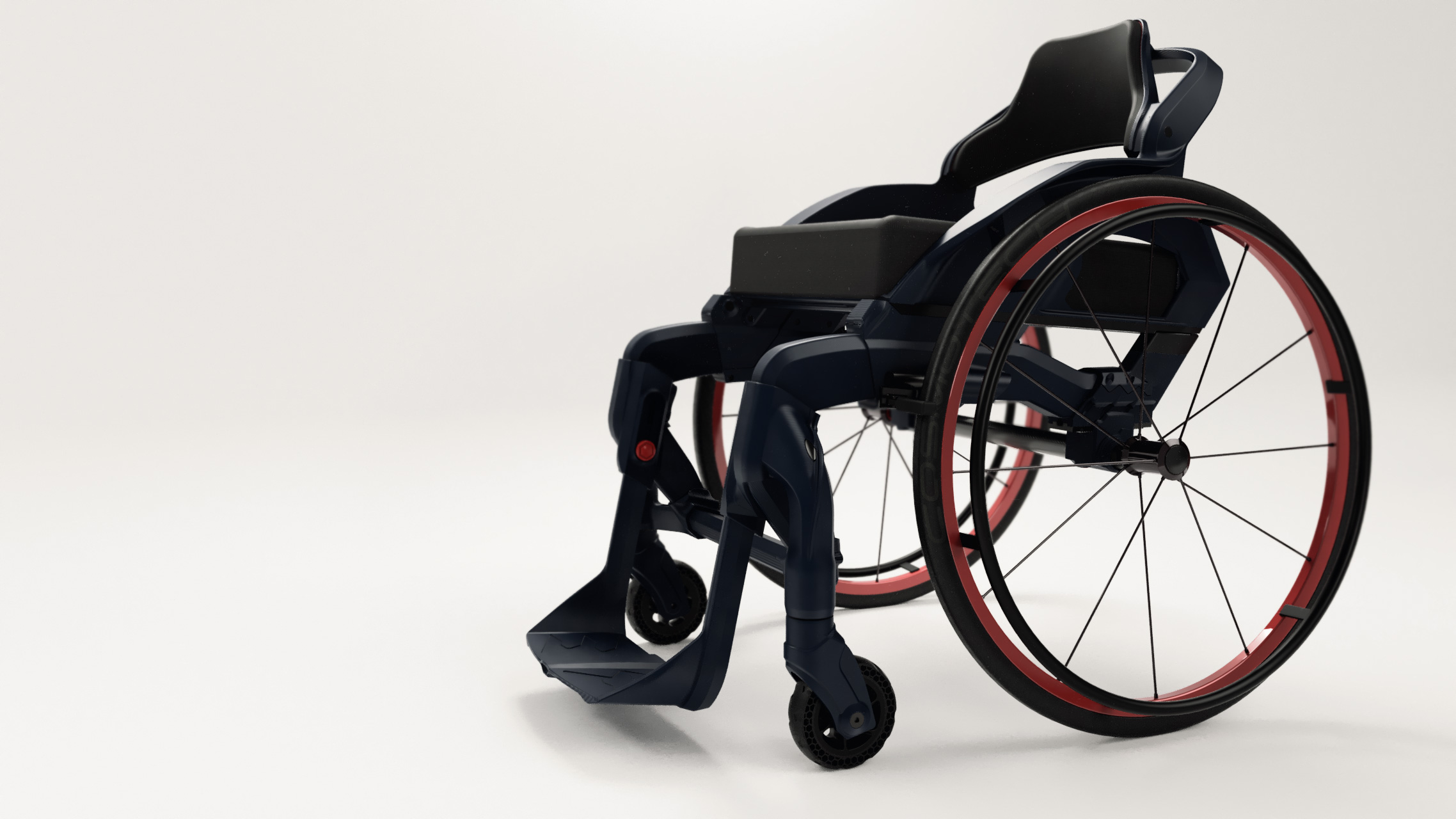
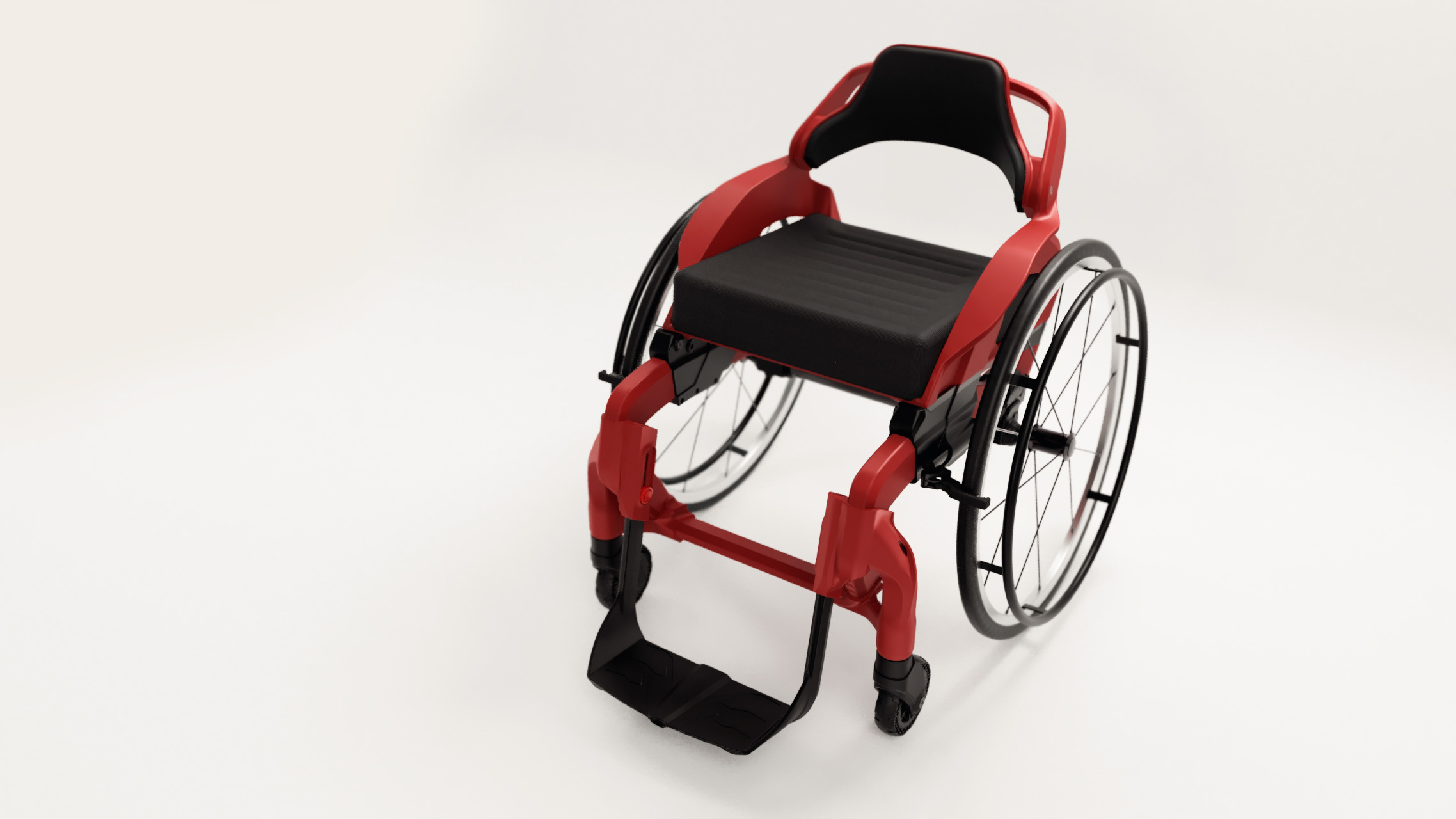
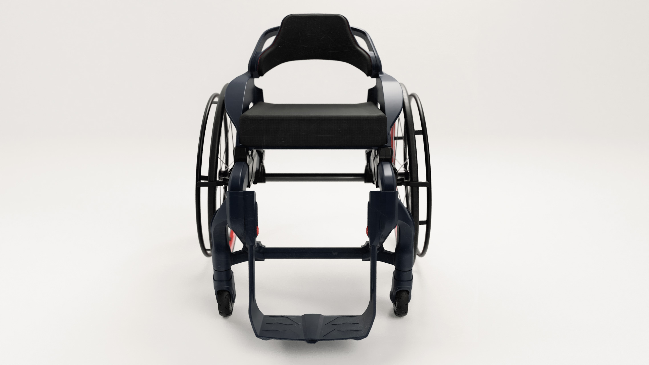
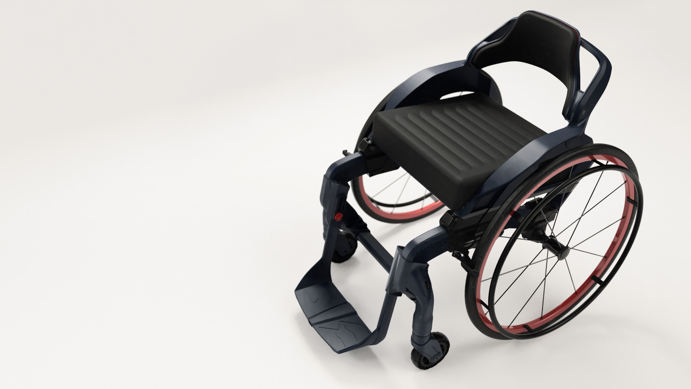
The Hammer is an experimental prototype, which was created with the concept of creating a wheelchair with an aggressive design. Its design distinguishes itself with strong lines inspired by sci-fi themes.
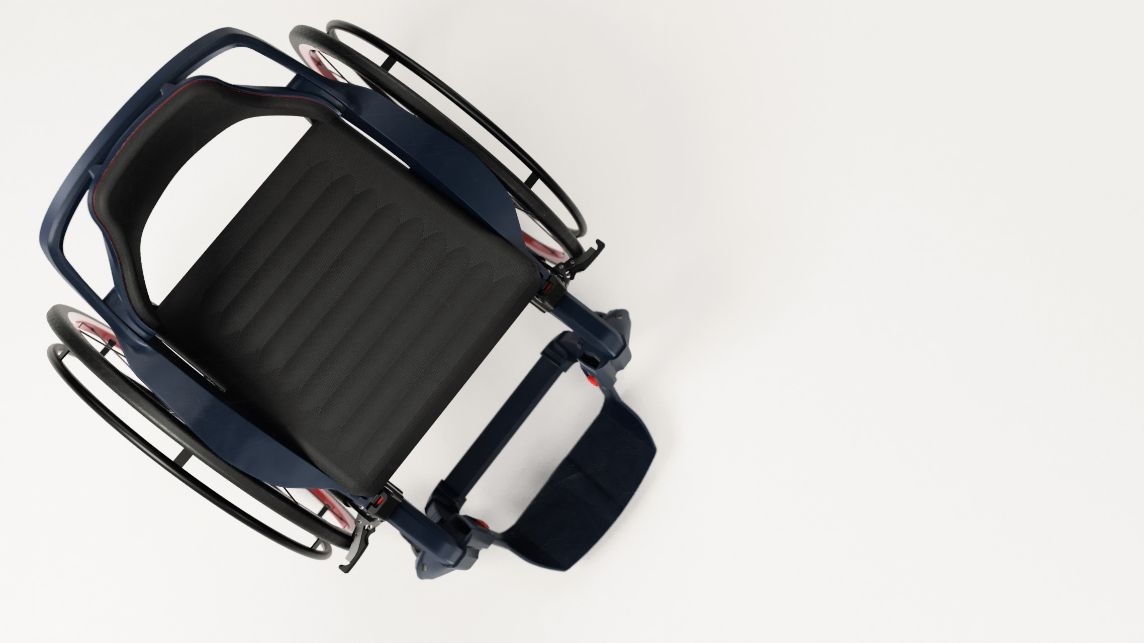
The wheelchair was designed to adapt to the user and his changing needs by adjusting the position of the centre of gravity and the position of the footrest. Moreover, thanks to the applied 3D printing technology, the design was created with the intention of adapting it to a specific person based on body scanning.
The Hammer is an experimental prototype, which was created with the concept of creating a wheelchair with an aggressive design. Its design distinguishes itself with strong lines inspired by sci-fi themes.
The wheelchair was designed to adapt to the user and his changing needs by adjusting the position of the centre of gravity and the position of the footrest. Moreover, thanks to the applied 3D printing technology, the design was created with the intention of adapting it to a specific person based on body scanning.

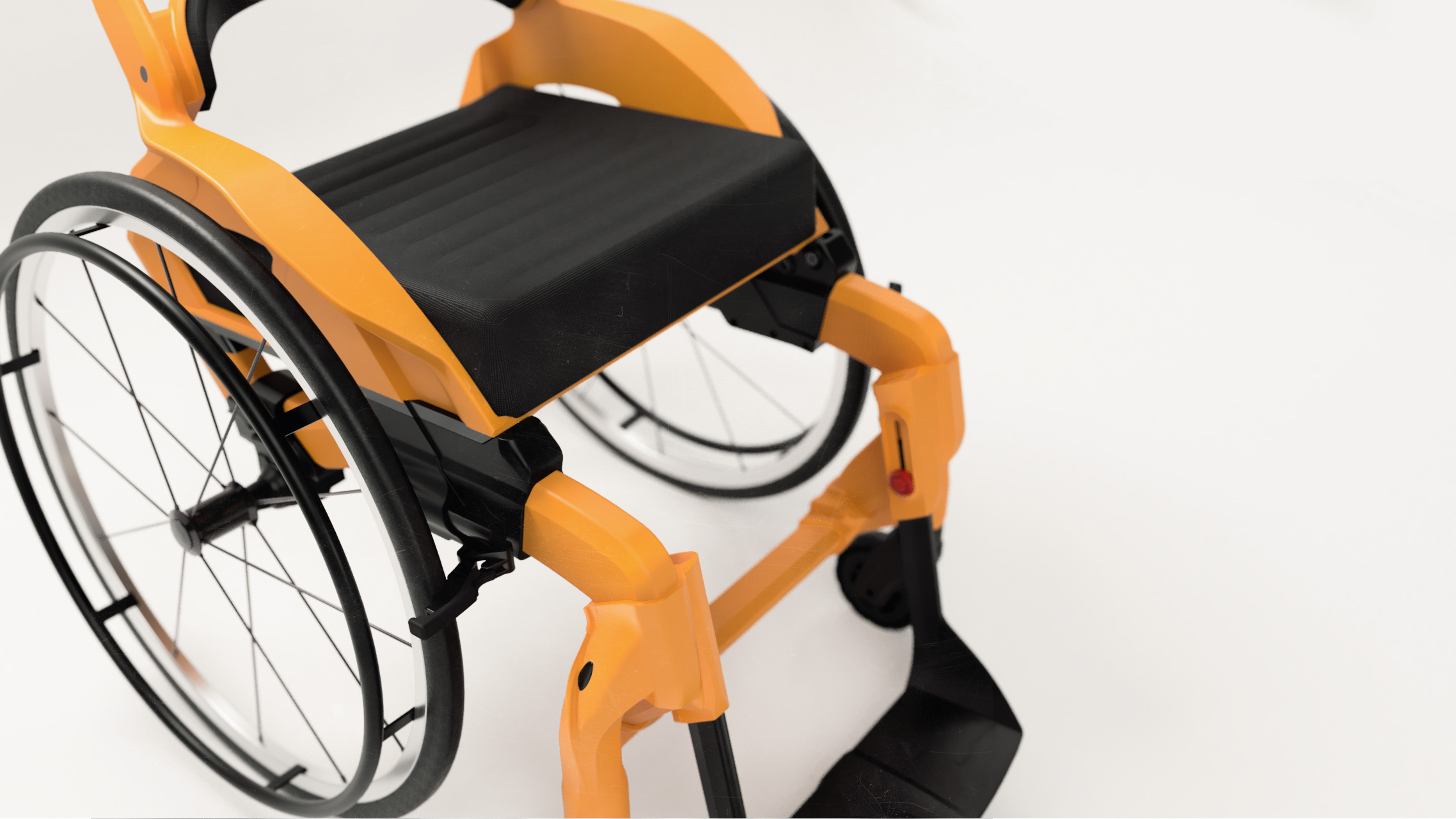
Durability and stiffness of the connections which enable the above-mentioned adjustment of the prototype’s geometry has been ensured by the implementation of metal elements in plastics, allowing to create durable detachable connections.
Durability and stiffness of the connections which enable the above-mentioned adjustment of the prototype’s geometry has been ensured by the implementation of metal elements in plastics, allowing to create durable detachable connections.
Prototypowanie za pomoca druku 3D
Like most of our prototypes, Hammer consists mainly of elements made using 3D printing. This method allows to create prototypes at a relatively low cost, with a high level of detail of the designed object. It allows to examine the geometry and stylistics, without disturbances resulting from the scale or lack of an appropriate point of reference occuring on computer visualizations. The assembly of a prototype also allows to verify the difficulties that may occur during the assembly of the finished product and introduce appropriate changes before incurring the costs associated with the implementation of production.
3D printing consists of successive overlapping of material layers. It is an additive technology, which means that as a result of this process the amount of material in the printer’s workspace increases. This process is the opposite of traditional subtractive manufacturing methods, in which the shape of the material is obtained by processing it with machining tools.
3D printing is a dynamically developing technology, divided into many methods. The most important of them are FDM, SLS and DLP.
FDM – Fused Deposition Modeling
In this method filament of the thermoplastic material is melted and then placed along the respective paths of the layer by squeezing it through the nozzle. Depending on the material, the melted filament cures under the influence of ambient temperature, or is continuously cooled by a fan mounted near the nozzle.
SLS – Selective Laser Sintering
Method involves bonding successive layers of powders by heating them to the appropriate temperature with a laser beam. This method allows for printing from both plastic and metal powders, creating high-strength structural elements with shapes difficult to obtain using traditional technologies.
DLP – Digital Light Processing
This technique consists of curing a liquid photo-curable resin with a light beam. The elements produced by this method are characterized by very smooth walls and high resolution, due to the low layer height.
Design
The process of creating physical objects with the use of 3D printing technology starts with the creation of a CAD project (Computer Aided Design) that adequately represents it. When designing a model for 3D printing, you must keep in mind parameters such as material shrinkage, height and thickness of the printing layer. These affect the dimensional accuracy of the component. The model can also be printed in various orientations that affect its strength, especially in FDM (Fused Deposition Modeling). The molten material is fed through the nozzle in layers and the connections between the layers are weaker than the layers themselves, as the molten material is laid on the material that has already solidified.
Slicer
The previously prepared model mesh then has to be imported into the slicer – software that translates 3D model into code for the printer. It has, among other things, commands controlling the workhead movement and print parameters such as temperature and speed. These programs, in addition to converting the model into a code that is compatible with the printer, also allow to add support materials that enable to print elements that would otherwise print “in the air”. Determining these printing parameters such as the temperature and speed of the head. Density of infill between external surfaces. Dimensions of the print path, as well as the percentage change of the model dimensions to compensate for material contraction.